|
|
|
|
|
Table containing some additional useful information:
|
[1]
|
U. Rohrer, Secondary Beam Line Computer Control at PSI.
Annex I of PSI Annual Report 1988, p.7-8 (21 kB)
|
| |
All 7 area server PCs have been replaced by new PCs running Windows XP-SP2 Professional as
Operating System (in a FAT32 partition). The PC cases are black or light-gray colored
rack-mountable 19" units. For more info press 'Used Computers' button. (No hardware watchdog
units are used anymore.)
|
| |
On all 7 area client PCs the Operating System has been upgraded from Windows 98 SE
to Windows XP-SP2 Professional running in a FAT32 (4 GB) partition. The RAM has been upgraded
from 128 to 256 MB and the Ethernet interface has been replaced with a modern 3Com 3C905CX-TX-M
PCI card.
|
| |
Each of the 7 secondary beam line 's device settings are logged every 20 secs.
These beam line data are kept in separate directories divided in up to 10 files of 1 MB size
each. Thus, depending on the number of devices, data for the last 3 to 6 days are stored.
You may access these logging data .
|
| |
2 spare PCs (server and client) are available for replacing temporarily a defective area or server PC.
Here some instructions on how to proceed.
|
| |
A flaw in the 'Rate Optimizing Program for a Secondary Beam Line' (Optima) has been corrected. Until now
the 6-fold scaler (S-500) has not been gated, which led occasionally to bad
normalized experimental rates and which therefore disturbed the automatic
search for the maxima. Now all 7 areas are equipped with an IO-50x unit
(must be located next to the scaler unit on the right side) which controls
the inhibit input of the scaler.
|
| |
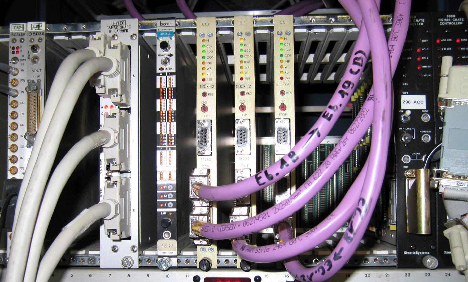
All 7 area-server PCs have been equipped with a second CAMAC server module
based on CORBA (Common Object
Request Broker Architecture), which is fully
multi-threaded. But in order to avoid conflicts inside the single-threaded
RS232 module between this new server and the standard TCP/IP CAMAC server
(both embedded in a Windows shell) a Critical Section Object (a component of
the shared memory structure "Cambuf") acting as a Mutex inside
the multi-threaded Camac-DLL code queues the accesses to the shared RS232
interface code (see Fig.5 (7 kB)).
CORBA allows telecommunicating with remote objects (servers) on a
relatively high level of abstraction. As CORBA implementation the freely
available
omniORB2 by AT&T (programmed in C++) has been chosen. In order to get
information about the number of connected hosts and their names and how
often they timed-out the omniORB2 API had to be expanded (by adding some code
and rebuilding the libraries). First tests with this new CAMAC server
(Server99.exe) show very encouraging results (stable operation and no side
effects so far). Code for a simple CORBA CAMAC test client is presented here
for C++ (AT&T's omniORB2) and for
Java (Sun's JDK/IDL). The Seondary Beam Line Programs "Set Point",
"Combi-Control", "Optima", "Magnet Cycling" and "Inter Active Camac Command"
are now also available in the "C++ Corba client" version.
|
| |
For the 4 Secondary Beam Line areas  E1, E5, M1 and µE4 it is
now possible to open and close the beam shutter(s) remotely. This is very useful for automatic
data taking in case you have to check there from time to time the background with a closed
beam shutter. The 3 other areas may also be connected to this feature if required by the
experimentalists. E1, E5, M1 and µE4 it is
now possible to open and close the beam shutter(s) remotely. This is very useful for automatic
data taking in case you have to check there from time to time the background with a closed
beam shutter. The 3 other areas may also be connected to this feature if required by the
experimentalists.
|
| |
The 4 Secondary Beam Line programs 'Set Point', 'Optima', 'Combi Control' and 'Magnet Cycling' may now be connected to up to
4 server PCs. Because of the added complexity, for each of the 4 programs the indication of the
server to which the page, group or device in use relates has been improved.
|
| |
At the 5 Secondary Beam Line areas µE4, M1, M3,
E1 and E5
the ROAD-bus has been replaced by the more reliable CAN-bus.
The 'Firmware' of the new CAMAC-to-CAN interface handles CAMAC-I/Os 100%-compatible with those of
the old CAMAC-to-ROAD interfaces. Therefore no program modifications had to be made. Only the local addresses
of the different power-supplies may eventually had to be changed (new device.lis). The remaining 2 areas will
eventually also be equipped with the new bus during the next shutdowns (probably one per year).
|
| |
In order to get a 16 times better resolution for some critical secondary beam line magnets, the "16/12 bits signed
combi controller" (type = 10) has been implemented. (This controller supports polarity switching
together with 16 bits DAC and 12 bits ADC resolution.)
The first magnets equipped with this controller type are the bending magnets ASK71 and ASK72
at the E3 area.
|
| |
In the M3 area the 3 bending magnets ASL31, ASL32 and ASK32 got
new power supplies each with a local DSP controller and an optical link to the CAMAC IP Carrier Board interface.
The IP (Industry Pack) firmware developped by Guido Janser is designd in such a way, that no modification of the
Control System Software for Secondary Beam Lines was necessary.
|