 In 1987 almost every secondary beam line at PSI was still controlled by a hardwired
ROAD-B command station with no built-in intelligence. During the year of 1988
these difficult to maintain command stations have been successively replaced by
Atari ST computers (MC68000 processor, 8 MHz, 1 MB RAM, ROM-TOS, 720 KB floppy
drive) interfaced via the modem port (19200 baud) to some new camac hardware
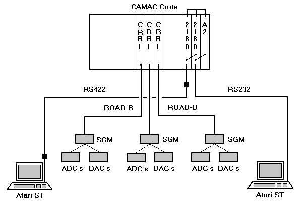
(see Fig. 1). As interface between the computer and the CAMAC dataway serves
a CES-2180 ACC (Starburst) with CATY on ROM as driving software. The ROAD-C DACs
and ADCs of each cluster of magnet power supplies are interfaced via a subgroup
master (SGM) and a ROAD-B highway cable with a special interface (CRBI) to a
CAMAC crate. All ROAD hardware has been developed by the Accelerator Control
Group.
 Whereas most of the user software for the Atari ST has been coded in Fortran,
some routines and utilities were written in Assembler, Basic or C. All programs
fit well onto one single micro floppy disk. During the cold start procedure,
the most important programs are copied onto a RAM disk of 500 KB size.
Therefore, there is no need for a hard-disk which makes the whole computer
control very handy and easy to transport into the barrack of the physics
experimentalist.
 All programs are data file driven, so changes to the hardware configuration are
quickly transferred to the software by just editing files without recompilation.
The programs, which also make full usage of the user friendly GEM software
layers (WIMP human interface), may be divided up into 3 different groups:

Figure 1: Block diagram of the new computer control for the 2 coupled areas
µE1 and  E1. Each area has its own Atari ST
computer. For distances longer than 30 m between computer and CAMAC crate,
RS232-to-RS422 boosters are used. The ROAD bus system could be taken over
almost unmodified from the former command stations.

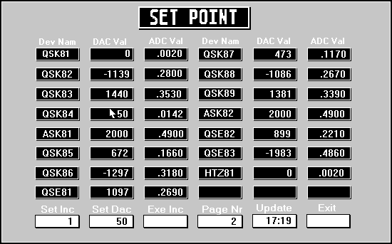
Figure 2: A typical screen output (monochrome, 640x400 pixels) produced by the Set Point program shows some actual settings of the µE1 magnets. The usage of the handy mouse allows the physicist to access the program's whole functionality in an easy way.
- Set-point program for individual control of all devices including saving current settings on or restoring old values from disk files. (see figure 2)
- Rate optimizing program which allows the user to bring up his experimental rate automatically to a maximum by executing a command file containing a list of the magnet elements the settings of which have to be adjusted.
- Transport program package (CERN/SLAC/FERMILAB version) which allows the experienced beam physicist to study or to debug online new optical modes or new beam lines. The DAC settings are readable or settable directly from the programs and converted via tables into physical units.
 Up to now this computer control has been tested and installed on 4 different
beam lines (
 M3,
M3,  E3, µE1
and
  E1) and was found to be working reliably. (Because
µE1 and
  E1 beam lines have 4 common magnets, they
are controlled from a single common CAMAC crate containing 2 daisy-chained
CES-2180 ACCs with 2 separate Atari ST computers, one for each area.) In case
of a rare system crash or hang-up, pressing one button boots the computer within
30 seconds. This computer control helps to bring up a beam line in a much
shorter period of time than previously, and makes it easier to control the
magnets during a data taking run, because among other things it alerts the user
if a device becomes faulty.

 Secondary Beam Line Control System:
 Home Page
![]()
![]() last updated by Urs Rohrer on 7-Feb-2006
last updated by Urs Rohrer on 7-Feb-2006