|
Question #1:

Is there a method to deliver short full intensity megawatt proton beam macro-pulses to the
planned Ultra Cold Neutron (UCN) source without a significant degradation
for the user communities at the targets M, E and SINQ ?
Answer:
Yes, indeed, mainly by the installation of a magnetic beam kicker into
the megawatt proton beam line just in front of the HE-beam-splitter (EHT4).
About tests with this new device see also the article from PSI Large Research
Facilities Scientific and Technical Report 2002, Volume VI,
First Beam Tests with the Fast Kicker
Magnet for the Ultra Cold Neutron Facility (pdf, 223 kB).
About some improvements for this device see also the article from PSI
Large Research Facilities Scientific and Technical Report 2004, Volume VI,
Improvements of the safety environment
for the UCN-Kicker Magnet (pdf, 575 kB). About the current status (May 2005) of the planned
macro-pulsed megawatt proton beam to UCN see the UCN TAC-Meeting report, May 12-13, 2005 (pdf, 3.9 MB, Power Point transparencies). For some additional
and partly historical info see collection of
eight reports about kicker and proton beam for UCN (pdf, 800 kB).
Details:
Within the next few years it is planned to place a source for ultra cold neutrons
(UCN) at the place of the former piotron. During operation every 10 minutes a
short pulse (not longer than a few seconds) of protons of 6 mAs charge should
be directed onto the target inside the source. Because the operation of the HE
accelerator complex is designed and optimized for a DC proton beam (with 50 MHz
structure) these requirements mean some new challenges and will require
a few modifications to be made at the 590 MeV high intensity megawatt proton beam lines. It is
assumed that the DC splitter (EHT4) has to stay in operation for several more
years, so a concurrent solution for DC and "pulsing" has to be searched for.
So far two quite different methods for producing 590 MeV megawatt proton beam macro pulses have
been proposed:
Method A:
The following sequence of actions should be initiated by a computer program
every 10 minutes.
- Turn off the proton beam onto targets M and E and SINQ.
- Set steering magnet SHC4x of the EHT4 to the value to produce 6 mrad
(NA direct beam).
- Crank up the proton beam intensity at Injector 2 as fast as possible to produce Q=6mAs
onto UCN target.
- Turn off the proton beam.
- Turn off SHC4x.
- Normal procedure to bring up the proton beam intensity onto targets M and E and SINQ.
(takes 30 seconds because of target E)
The current layout of the megawatt proton beam line around the HE-beam splitter
(EHT4) with SHC4x and the magnetic septum ABS is shown in Fig. 1 (38 kB). The duration of the above described
procedure is estimated to last not much less than 60 s. It is also assumed that
(because of beam loading effects in the ring cavities and delays caused by proton beam
centering processes) the proton beam intensity cannot be raised faster than with 200 µA/s
so that the 6 mAs will be reached only after 8 s by just reaching 1.5 mA peak current.
This procedure will therefore reduce the availability of the proton beam on targets M, E and SINQ
by about 10 % and keep the mean time between failures (MTBF) at the low value of 10 min,
whereas already today, often during night shifts and over weekends it is found to be at 2
hours or even above.
Because no continuous proton beam of high intensity (megawatt) onto the target of UCN can be made
(thermal and shielding constraints), it is not possible to study the behavior
of the steering effects during the cranking-up procedure of the proton beam intensity
from injector 2. Because of all these reasons method A seems not to be very
attractive but cheap and possibly dangerous (has been discarded by now).
Method B:
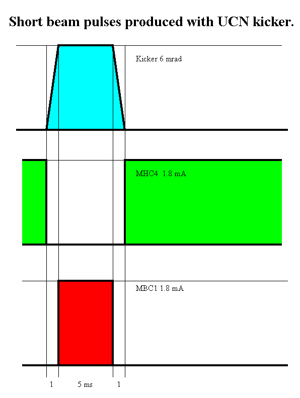
A fast kicker magnet (rise time < 1 ms is producing short (t = 5 ms ÷ 8 s)
macro pulses of full proton beam intensity onto the target of the UCN source. Because of
proton loss considerations the only position for a kicker is just in front of
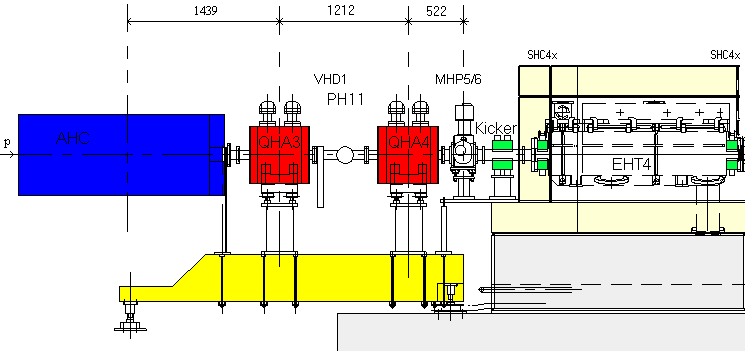
EHT4. The modified layout of the elements between AHC and EHT4 is drawn in
Fig. 2 (11 kB). Space
for the magnetic kicker is made by shifting QHA4 together with MHP5/6 some 40 cm
closer towards QHA3. To gain this space the vacuum pump (PH11) and the vacuum
valve (VHD1) have to be replaced by new models which require less space. The
vacuum chamber at the location of the kicker has to consist of some sort of
insulator like ceramics in order to avoid eddy currents which could slow down
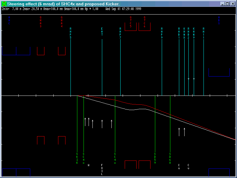
the kicking process. The steering effects of the splitter steering magnet (SHC4x)
and the proposed kicker magnet in front of EHT4 (both 6 mrad) are compared in
Fig. 3 (16 kB). Both
produce a deviation of 40 mm at the location of the magnetic septum (ABS)
which is required to get around its entrance collimator of 20 mm width.
(Eventually the 2 present SHC4x steering magnet halves could be replaced by 2 new
kicker magnets with ferrite yokes. But the stainless steel vacuum chamber of
EHT4 will probably prevent fast rise times because of eddy currents.) The big
advantages of the fast kicker method are, that it does not interfere with the
accelerators and hardly diminishes the proton beam availability figure.
Megawatt Proton Beam spill considerations (with method B) :
During the transition of the megawatt proton beam between the targets and UCN
half of the megawatt proton beam will be lost at the entrance collimator of the magnetic
septum (ABS). The rest will be lost along both proton beam lines. But because of the
fast transition time no interlock will be triggered during this time (< 1 ms).
Unfortunately the kicked high intensity proton beam at the exit of EHT4 will be 7 mm further to the
right than the proton beam deflected with SHC4x. Thus, for about 3 s every 10 minutes
the kicker will produce some losses by protons hitting the EHT foils sitting
in park position. ( With a megawatt proton beam size of 4 sigma = 20 mm all protons to the
right of 3.4 sigma [340 ppm] will hit the splitter foil array and therefore be
lost. See Fig.3. ) These losses could be reduced significantly by shifting the
park position of EHT4 some 5 to 10 mm to the right and/or the proton beam center
to the left. On the other hand, because of the low duty factor of only about
0.5 % these losses do not mean a big threat for the irradiated components,
because they are comparable with the losses of the DC-splitting.
Method B seems to be quite attractive but not cheap.
Megawatt Proton Beam optics and centering:
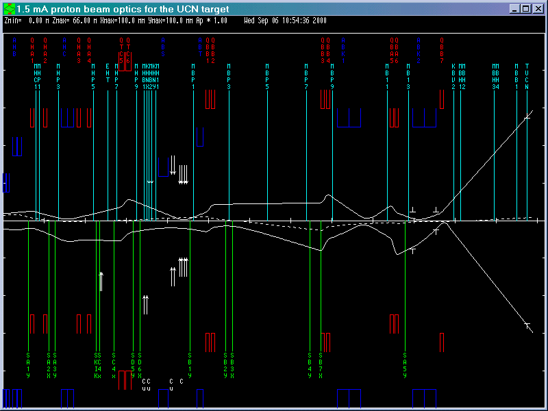
A possible proton beam envelope of the 1.5 mA proton beam intensity between the high intensity ring cyclotron
extraction and the planned UCN target is shown in
Fig. 4 (31 kB).
The megawatt proton beam at the target (lead) of the UCN source is assumed to be about circular
with a 4-sigma diameter of 11 cm. The correctness of the computed proton beam envelope
(extrapolated from data gained with the megawatt proton beam on target M) should be checked with
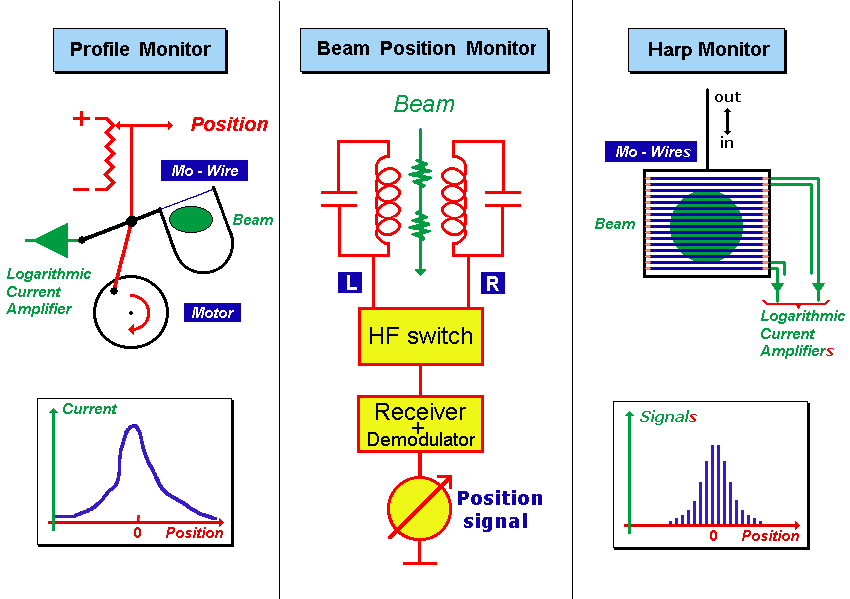
megawatt proton beam pulses of short duration (5 ms) and for that reason 2 pairs
of harp monitors (present profile monitors will not work) are placed
after ABK2. Additionally, the present electronics for the BPMs (beam
position monitors) has to be replaced through a faster one (1 KHz) in order to
be capable to detect the proton beam centers during some short (5 ms) high intensity
test megawatt proton beam pulses [required for centering the proton beam
see Fig. 5 (10 kB)].
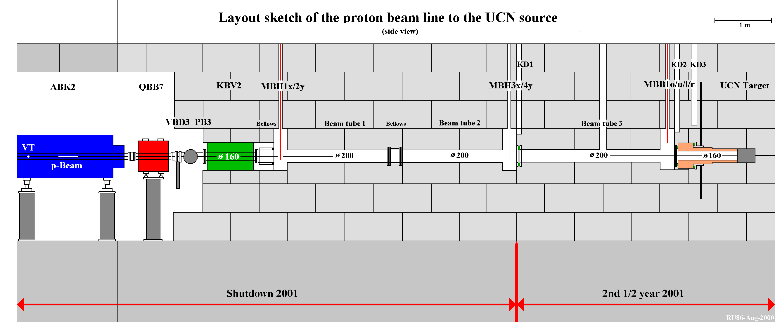
A sketch of the layout of the proton beam line between ABK2 and the UCN-target is shown in
Fig. 6 (61 kB).
Question #2:
What are the differences of the beam parameters for the high intensity proton beam line to SINQ caused by the
different lengths of target E (40 and 60 mm graphite) ?
Answer:
No significant differences of the proton beam diameters along the proton beam line and at the SINQ target
have to be achieved for the 2 modes. The settings of the bending magnets and quadrupoles differ
by about 0.845 % in order to compensate for the differences in momenta. Additionally the settings
of QHG23, QHG24, QHI27 and QHI28 have to differ further due to the different amount of angular
straggling at the target E. The proton losses along the high intensity beam line in the beam-cellar are
expected to be about equal with the 40 mm and the 60 mm target.
Details:
Table 1 compares some of the basic parameters for the 2 target thicknesses.
Fig. 7 (27 kB) shows the 2
computed 2 proton beam envelopes for the 2
target E thicknesses (42 and 60 mm). The shown envelopes between Target E and
Collimator 3 (KHE3) are backward-extrapolations and correspond to the 2
transmitted proton beams (transmission = 57.5 or 69.3 %). In reality the proton beams in
this section are wider. Table 2 shows the bending magnet and quadrupole
settings for the 2 different lengths of target E. Of course, the 42 mm settings
have to be verified with some tuning and may finally change slightly. Also
the settings of the 5 steering magnets and the 2 pairs of halo-scraper slits
(not included in table 2) have to be tuned. proton beam envelopes for the 2
target E thicknesses (42 and 60 mm). The shown envelopes between Target E and
Collimator 3 (KHE3) are backward-extrapolations and correspond to the 2
transmitted proton beams (transmission = 57.5 or 69.3 %). In reality the proton beams in
this section are wider. Table 2 shows the bending magnet and quadrupole
settings for the 2 different lengths of target E. Of course, the 42 mm settings
have to be verified with some tuning and may finally change slightly. Also
the settings of the 5 steering magnets and the 2 pairs of halo-scraper slits
(not included in table 2) have to be tuned.
Table 1: Basic parameters for the 2 target thicknesses.
| Target E thickness (mm) |
60.0 |
42.0 |
| Momentum p (GeV/c) |
1.1713 |
1.1812 |
| Momentum loss @TE (MeV/c) |
32 |
21 |
| Energy loss @TE (MeV) |
25 |
16 |
| y' (2-sigma) (mrad) |
8.28 |
8.02 |
| x' (2-sigma) (mrad) |
11.64 |
10.37 |
| Losses @ 0.1 mA (%) |
39.1 |
28.2 |
| Losses @ 1.5 mA (%) |
42.5 |
30.7 |
Table 2: Bend and Quad settings for the 2 target thicknesses.
| Target thickness (mm) |
60.0 |
42.0 |
| AHL |
-53533 |
-53985 |
| AHM |
55262 |
55729 |
| AHN |
51466 |
51901 |
| AHO |
54764 |
55227 |
| QHG21 |
-3049 |
-3075 |
| QHG22 |
3002 |
3027 |
| QHG23 |
-3091 |
-3125 |
| QHG24 |
2670 |
2691 |
| QHI25 |
1166 |
1176 |
| QHI26 |
-1847 |
-1863 |
| QHI27 |
2003 |
2018 |
| QHI28 |
-2587 |
-2599 |
| QHI29 |
2876 |
2902 |
| QHJ30 |
-3184 |
-3211 |
| QHJ31 |
2802 |
2826 |
| QHJ32 |
-3685 |
-3716 |
Question #3:
Is it possible to run the full intensity megawatt proton beam onto the SINQ
target without any target inside the Target station E (2 mA, 1.2 MW) ?
Answer:
No, definitively not ! The proton beam losses down in the beam-cellar would be
to high.
Details:
With no target in place the x' of the megawatt proton beam leaving the target station E is
only about 3.5 mrad instead of 10.0 mrad with a C target of about 60 mm length
in place. Therefore the proton beam is 3 times narrower without a target than with a
target. This means that the proton beam density at the SINQ target would be 10 times
larger without a target, which is not permitted. To prevent this, the quadrupole
settings along the high intensity beam line have to be adjusted to such values that the proton beam
envelope gets blown up to about the same amount as with the target E in place.
But for this case the proton beam tails do not get cut off anymore by the collimator
system (100 % transmission). The profiles remain almost Gaussian and as a
consequence, the relatively large ratio of proton beam width to beam tube diameter
will produce unacceptably big proton beam lossess (and therefore activation)
along the high intensity proton beam line in the beam-cellar. To prevent this, the proton beam would have to
be kept narrower, and in order to avoid an excessive energy density at the SINQ
target the proton beam current would have to be reduced accordingly.
 Last updated by
Urs Rohrer on 17-April-2007
Last updated by
Urs Rohrer on 17-April-2007
|

 Go to question #1: UCN with magnetic kicker.