|

 The starting point of this low intensity (0.1 - 20 µA) beam line is considered to be at the magnetic
septum (ABS) and it ends at the Pirex target station, totaling a length of 45 m. The beam
envelope ( Fig.1: 20 kB )
is usually very narrow ( projected emittance less than 1
The starting point of this low intensity (0.1 - 20 µA) beam line is considered to be at the magnetic
septum (ABS) and it ends at the Pirex target station, totaling a length of 45 m. The beam
envelope ( Fig.1: 20 kB )
is usually very narrow ( projected emittance less than 1  mmmrad)
and may change from day to day, because this beam is made by cutting off
only about 1 % of the main high intensity megawatt beam (1.8 mA).
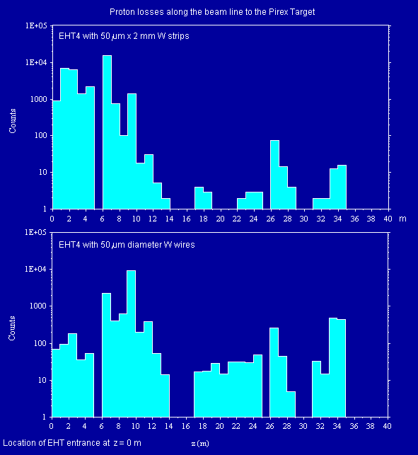
The dominating problem of this beam
line is the activation generated by the relatively high splitter (EHT) losses.
When cutting off 20 µA from the 1.8 mA main beam as much as 2 µA of
the protons are making head on collisions with the septum (wires or strips) as
has been established some time ago through measurements by M. Olivo.
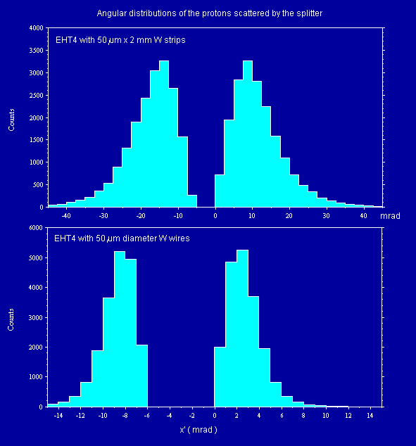
All protons making head on collisions with the EHT are lost, as can be shown
with the Monte Carlo program Turtle. The angular straggling distribution of these
protons depends on the material (tungsten or molybdenum) and its distribution
along the beam axis (wires or strips of different dimensions). If the angular
distribution is narrow (wires), the protons may hit the vacuum tube as far away
as in the vicinity of the bending magnet ABK1. If the angular distribution is broad
(W strips), then most lost protons hit the tube before the ABS magnetic septum.
For the 2 computed proton loss distributions along the beam line
see Fig.2 (10 kB) and for the 2 computed angular distributions of the
scattered protons at the splitter exit see Fig.3 (8 kB).
Incidentally, half of the spilled protons make the way along the main beam line
before Target M and mess up this beam line section as well.
In our case the foil splitter is better, because it is easier and cheaper to
radiation-harden the region between EHT and ABS instead of the whole rest further
down stream.
This radiation-hardening and other improvements have been done during the
shut-down 1997/98 (duration was 6 months [January-June 98]. The performance
of this newly built section has proven to be quite good (as expected).
See also Fig.4 (43 kB)).
mmmrad)
and may change from day to day, because this beam is made by cutting off
only about 1 % of the main high intensity megawatt beam (1.8 mA).
The dominating problem of this beam
line is the activation generated by the relatively high splitter (EHT) losses.
When cutting off 20 µA from the 1.8 mA main beam as much as 2 µA of
the protons are making head on collisions with the septum (wires or strips) as
has been established some time ago through measurements by M. Olivo.
All protons making head on collisions with the EHT are lost, as can be shown
with the Monte Carlo program Turtle. The angular straggling distribution of these
protons depends on the material (tungsten or molybdenum) and its distribution
along the beam axis (wires or strips of different dimensions). If the angular
distribution is narrow (wires), the protons may hit the vacuum tube as far away
as in the vicinity of the bending magnet ABK1. If the angular distribution is broad
(W strips), then most lost protons hit the tube before the ABS magnetic septum.
For the 2 computed proton loss distributions along the beam line
see Fig.2 (10 kB) and for the 2 computed angular distributions of the
scattered protons at the splitter exit see Fig.3 (8 kB).
Incidentally, half of the spilled protons make the way along the main beam line
before Target M and mess up this beam line section as well.
In our case the foil splitter is better, because it is easier and cheaper to
radiation-harden the region between EHT and ABS instead of the whole rest further
down stream.
This radiation-hardening and other improvements have been done during the
shut-down 1997/98 (duration was 6 months [January-June 98]. The performance
of this newly built section has proven to be quite good (as expected).
See also Fig.4 (43 kB)).
![]() This section of low intensity beam line could not be used from January 2006 until most of 2007, because the former Pirex target station
had to be dismantled. During 2006 medical proton therapy got its own cyclotron (see Proscan project
layout).
This section of low intensity beam line could not be used from January 2006 until most of 2007, because the former Pirex target station
had to be dismantled. During 2006 medical proton therapy got its own cyclotron (see Proscan project
layout).
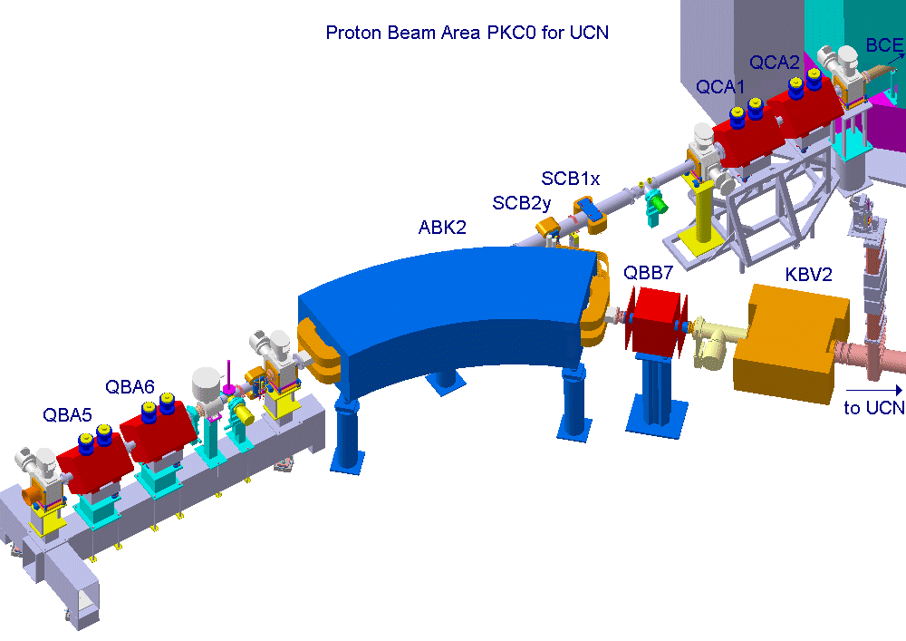
![]() Starting in October 2007 this section of beam line was used again for beam tests with the
pulsed high intensity
proton beam (pdf of 3.9 MB) for the Ultra Cold Neutron (UCN) source.
For these test purposes a beam dump (BCE) designed for a maximum of 25 µA was installed
at the location of the former Pirex target station in the PKC0 area.
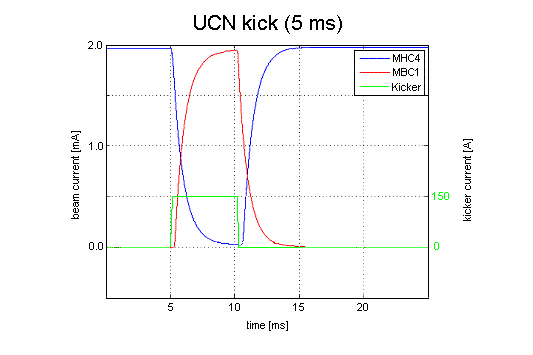
After some initial tests with beam peeled off from the 2 mA main beam with the DC-splitter (EHT) and intensities up to 10 µA, the full intensity beam
of 2 mA was routinely kicked for 5 to 10 ms onto this beam dump (BCE) in order to test the time response of the different beam diagnostic elements
(BPMs, beam current monitors, transmission monitors, loss monitors). As an example a time chart of the beam currents
MHC4 (Target M) and MBC1 (BCE beam dump) during a 5 ms kick (with 153 A kicker magnet current for 6 mr deflection angle) is shown.
Starting in October 2007 this section of beam line was used again for beam tests with the
pulsed high intensity
proton beam (pdf of 3.9 MB) for the Ultra Cold Neutron (UCN) source.
For these test purposes a beam dump (BCE) designed for a maximum of 25 µA was installed
at the location of the former Pirex target station in the PKC0 area.
After some initial tests with beam peeled off from the 2 mA main beam with the DC-splitter (EHT) and intensities up to 10 µA, the full intensity beam
of 2 mA was routinely kicked for 5 to 10 ms onto this beam dump (BCE) in order to test the time response of the different beam diagnostic elements
(BPMs, beam current monitors, transmission monitors, loss monitors). As an example a time chart of the beam currents
MHC4 (Target M) and MBC1 (BCE beam dump) during a 5 ms kick (with 153 A kicker magnet current for 6 mr deflection angle) is shown.
For some additional and partly historical info see collection of eight reports about kicker and proton beam for UCN (pdf of 800 kB).
| The proton losses along the beam line produced by spill of the splitter were computed with the computer code Graphic Turtle which is available electronically for various PC operating systems. |
 590 MeV Proton Beam Lines: Home Page.
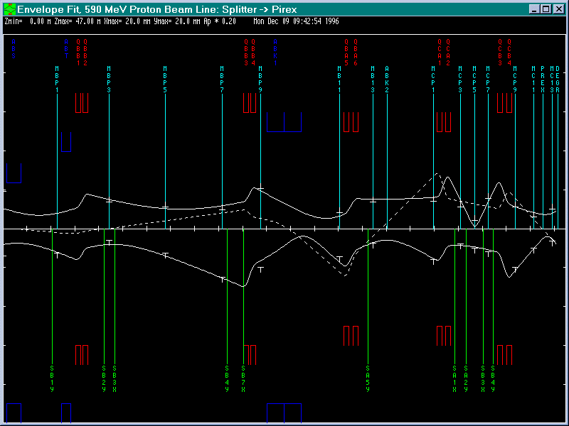
![]()
![]() Last updated by
Urs Rohrer on 9-Jan-2008
Last updated by
Urs Rohrer on 9-Jan-2008