|
 This first section of the 590 MeV High Intensity Proton Beam Line Channel is 43 meters long and its main
components are 5 bending magnets, 12 quadrupol lenses, 12 (horizontal and
vertical) steering magnets, 11 horizontal and 11 vertical
profile monitors. The goal is to transport the high intensity proton beam
with as little proton beam losses as possible (1 nA/m or 0.6 W/m) to the thin target station M
and focus it there with a spot size as small as possible (
This first section of the 590 MeV High Intensity Proton Beam Line Channel is 43 meters long and its main
components are 5 bending magnets, 12 quadrupol lenses, 12 (horizontal and
vertical) steering magnets, 11 horizontal and 11 vertical
profile monitors. The goal is to transport the high intensity proton beam
with as little proton beam losses as possible (1 nA/m or 0.6 W/m) to the thin target station M
and focus it there with a spot size as small as possible ( =1 mm).
The shown proton beam envelopes ( Fig.1: 23 kB )
represent a Transport envelope fit with the actual proton beam widths
(little 'T's in the display) measured with the profile monitors at 1500 µA. =1 mm).
The shown proton beam envelopes ( Fig.1: 23 kB )
represent a Transport envelope fit with the actual proton beam widths
(little 'T's in the display) measured with the profile monitors at 1500 µA.
The lower half-plane
represents the horizontal envelope, the upper half-plane the vertical envelope.
The dotted line is the assumed 0.1 % dispersion trajectory of the proton beam, whose starting values
R16 and R26 together with dp/p (near 0.1 %) are also varyed in the envelope fit
procedure in order to get an excellent chi-squared.
The horizontal projected emittance is about 2 mmmrad,
whereas the vertical one is only about 1 mmmrad.
The horizontal 4 width of the
proton beam at the location of the proton beam splitter (EHT) has to be kept around 20 mm,
because the aperture of this device is only 60 mm. With the exception of the
extraction magnets AHA and AHB the apertures are otherwise between 90 and 150 mm.
The 4 width of the proton beam at the Target M is usually smaller
than 4 mm in both directions. In order to fulfill this condition, the proton beam
has to be relatively 'steep' in front of Target Station M. With the help of a Transport
envelope fit with measured proton beam widths as constraints,
the position of the double waist at the target M location can be determined
through extrapolation to an accuracy of about ±5 cm. With the same method the width
and the height of the proton beam at the splitter position may be adjusted to the desired values. mmmrad,
whereas the vertical one is only about 1 mmmrad.
The horizontal 4 width of the
proton beam at the location of the proton beam splitter (EHT) has to be kept around 20 mm,
because the aperture of this device is only 60 mm. With the exception of the
extraction magnets AHA and AHB the apertures are otherwise between 90 and 150 mm.
The 4 width of the proton beam at the Target M is usually smaller
than 4 mm in both directions. In order to fulfill this condition, the proton beam
has to be relatively 'steep' in front of Target Station M. With the help of a Transport
envelope fit with measured proton beam widths as constraints,
the position of the double waist at the target M location can be determined
through extrapolation to an accuracy of about ±5 cm. With the same method the width
and the height of the proton beam at the splitter position may be adjusted to the desired values.
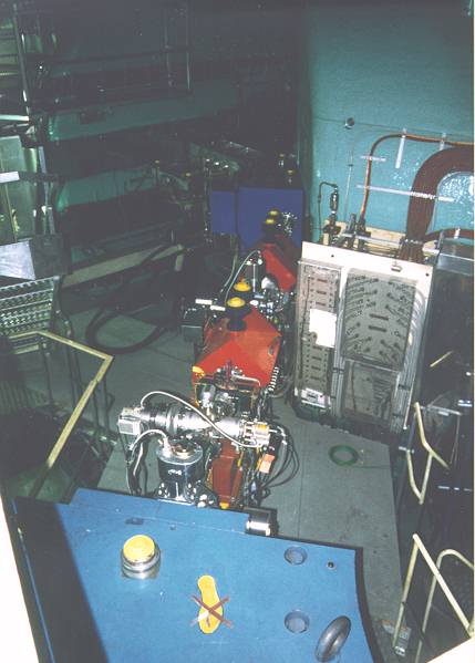
In Fig.2, (37 kB) one can see the
high intensity proton beam line from the ring extraction (vacuum flange of AHA) to the bending magnet AHC
(blue, partly in the foreground). In between there are the bending magnet AHB (blue),
2 quadrupoles QHA1 and QHA2 (red), 2 pairs of profile monitors and a turbo molecular vacuum
pump. At the right a sector magnet of the ring cyclotron is partly visible.
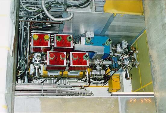
Fig.3, (40 kB) shows the adjacent
region of the splitter (EHT) as it looked before the modifcations done in the
shutdown 1997/98 with its position control gear mounted on the wall to the left
and with virtually no local shielding in this region. In the foreground the
quadrupole QHA4 and in the background behind the EHT vacuum chamber the 2
quadrupoles QHB5 and QHB6 are visible. The losses produced by the splitter
are as high as 2 µA.
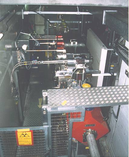
Fig.4, (40 kB) shows a top view
of a short section of this high intensity proton beam line (SHB7x + QHB7 + QHB8) together with a
short section of the neighboring (low intensity) proton beam line (ABT + QBB1 + QBB2) leading to the
pirex target station. The narrow spatial situation in which the visible 6
magnetic components are (causing some maintenance problems) can well be
seen.
The region between the bending magnet AHC and the magnetic septum ABS has been
modified in the shutdown 1997/98. This was mainly done in order to radiation
harden the components after the EHT splitter and to reduce the proton losses
along the proton beam line leading to the pirex target. Fig.5
(43 kB) shows the new mechanical design. An important constraint
for the new layout was the need to stick as close as possible to the former
optical conditions. This means that the new quadrupoles, steering magnets and
profile monitors remained as close as possible at the locations of the replaced
elements. Two important new components are the 2 movable pairs of slits (KHNX1
and KHNY2 at the location of the former BH1) which offer the possiblity to trim
the proton beam halo produced by the splitter (and therefore the activation further
downstream) as much as possible.
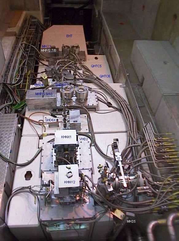
Fig.7 (59 kB) shows a top view of the
new EHT region just after completion of the installation work. What you see are
mainly the white top surfaces of the shielding blocks (concrete, steel or
marble) a vacuum pump, the motors, some covers, the electrical cabeling, water
and vacuum hoses, compressed air and water pipes leading to or sitting on top
of the different devices integrated into the shielding blocks. Tags with the
names of the devices have been drawn on top of each unit into the photograph
in order to get some orientation. The shown piece of rebuilt proton beam line will
finally be covered (like the already existing rest) by some more local shielding
consisting of several layers of concrete blocks.
Since this newly built-in section is in operation, the overall performance of it
has proven to be quite good (as expected). See also
PSI Scientific and Technical Report 1998 Volume VI (Large Research Facilities) on
pages 14, 15.
 Last updated by
Urs Rohrer on 7-Jan-2008
Last updated by
Urs Rohrer on 7-Jan-2008
|


 590 MeV High Intensity Proton Beam Lines: Home Page.
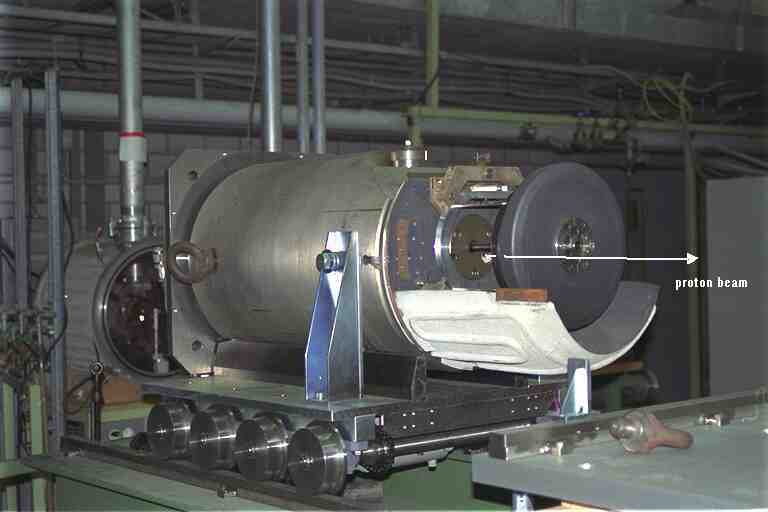