|
 This second section of the 590 MeV Proton Channel is 18 m long
and transports the beam with the help of 2 quadrupole triplets from the
target station M (Mince=thin) to the
target station E (Epais=thick). 6 horizontal,
6 vertical profile monitors, 2 horizontal and 2 vertical steering
magnets are additional devices belonging to this section. The
first triplet is set to such field values that the beam forms
an intermediate double waist half way between target station M and target station E
( Fig.1: 16 kB ) .
This second section of the 590 MeV Proton Channel is 18 m long
and transports the beam with the help of 2 quadrupole triplets from the
target station M (Mince=thin) to the
target station E (Epais=thick). 6 horizontal,
6 vertical profile monitors, 2 horizontal and 2 vertical steering
magnets are additional devices belonging to this section. The
first triplet is set to such field values that the beam forms
an intermediate double waist half way between target station M and target station E
( Fig.1: 16 kB ) .
Three profile monitor
pairs are placed around this waist location in order to allow
a pretty accurate determination of the projected emittances
(around 8 mmmrad in both directions)
and the position of the waists. Thus, also a rather precise
extrapolation of the sizes and positions of the 2 target waists is possible.
The horizontal 4 mmmrad in both directions)
and the position of the waists. Thus, also a rather precise
extrapolation of the sizes and positions of the 2 target waists is possible.
The horizontal 4 width of the
beam at the location of Target station E is around 3 mm, whereas in vertical
direction the 4 width is around 5 mm. width of the
beam at the location of Target station E is around 3 mm, whereas in vertical
direction the 4 width is around 5 mm.
Just in front of Target station E there is the high acceptance extraction magnet
(AHSW41) for the E5 secondary beam line. The fringe
field of this magnet deviates the proton beam up to ±6 degrees. Therefor 2
additional compensation magnets (AHU and AHV) are required to keep the beam
on the axis after Target station E ( see Fig.2, 57 kB).
The 3 bending magnets are controlled with 3 'super-knobs' to facilitate easy
tuning and to avoid dangerous wrong settings.
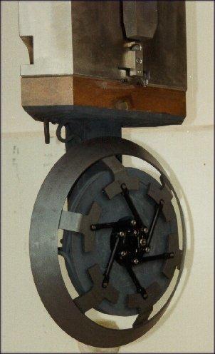
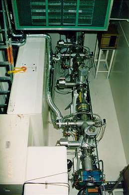
Fig.3 (19 kB) shows a top view picture
of the old section between the 2 quadrupole triplets. This design stems from the time with only
0.1 mA of proton beam intensity.The 3 pairs of profile
monitors (MHP25-MHP30) with 2 turbo molecular pumps between them can be seen
as well as the 2 steering magnets (SHB13y + SHB14x) on the bottom of the
picture.
Fig. 4 (55 kB) shows a top view picture of
the new design commissioned in May 2001. Sketches of how it would have to look like
are already existing since 1996. Fig. 5 (53 kB)
shows a side view and Fig. 6 (39 kB)
a top view of the new layout.
The design of some components (mainly steering magnets, profile and beam center monitors,
vacuum components) has been developed for the splitter region modification and could be re-used
here for this beam line section. See also
PSI Scientific and Technical Report 2001 Volume VI (Large Research Facilities) on
pages 31, 32.
 Last updated by
Urs Rohrer on 27-Mar-2006
Last updated by
Urs Rohrer on 27-Mar-2006
|

 590 MeV Proton Beam Lines: Home Page.
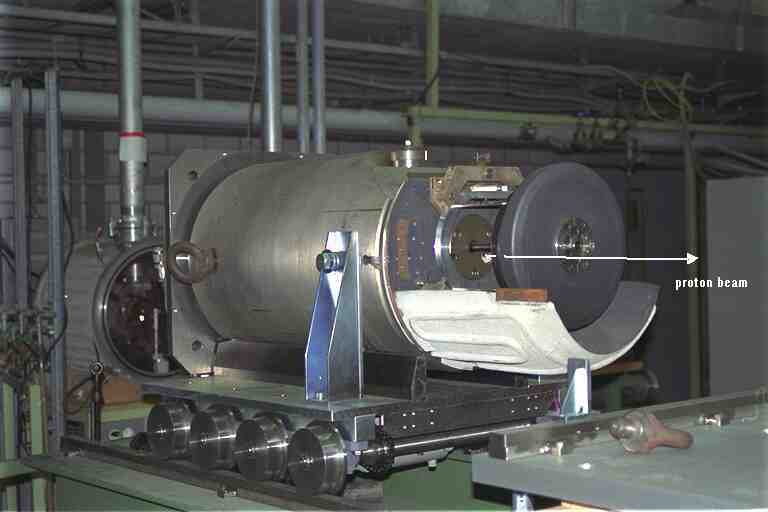