|

 This section of the 590 MeV Proton Beam Line Channel is 55 meters long and its main components
are 4 bending magnets, 12 quadrupol lenses, 9 (horizontal and vertical)
profile monitors (no beam position monitors available for
this proton beam line), 5 horizontal steering magnets, 7 collimators and 2 pairs of slits.
The goal is to reshape the proton beam after the passage through
target E (4 or 6 cm [1]) with
collimators and slits and transport the remaining part of the proton beam (57 % for
6 cm or 70 % for 4 cm carbon at the Target station E)
to the SINQ target (see also proton beam line Target station E -> Beam Dump)
with as little losses as possible in the second half of the proton beam line.
Optically this proton beam line consists of a long stretched "Z" and a flat "U".
Because the protons have to enter the
SINQ target station
perpendicular from below the target, the whole proton beam line is turned into a vertical plane.
Just under the target 3 collimators prevent the back scattered neutrons from
activating the proton beam line components below and avoid the deposition of protons
at the rim of the entrance window of the SINQ target. Electrodes mounted in front of all 3 collimators
(MHB's) allow monitoring position and width of the proton beam.
This proton beam line consists of 2 locally separated parts, the first behind target station E
is in the experimental hall, the second one in a 11 m deep channel below the
SINQ target hall. Both parts are connected together via a 12 m long drift tube
embedded in a tunnel inclined by 28 degrees against the horizontal. See
Fig.1 (43 kB) for more details.
The projected emittance in both directions are given by the blow up at target
E and the subsequent trimming through an elliptical collimation system
(14
This section of the 590 MeV Proton Beam Line Channel is 55 meters long and its main components
are 4 bending magnets, 12 quadrupol lenses, 9 (horizontal and vertical)
profile monitors (no beam position monitors available for
this proton beam line), 5 horizontal steering magnets, 7 collimators and 2 pairs of slits.
The goal is to reshape the proton beam after the passage through
target E (4 or 6 cm [1]) with
collimators and slits and transport the remaining part of the proton beam (57 % for
6 cm or 70 % for 4 cm carbon at the Target station E)
to the SINQ target (see also proton beam line Target station E -> Beam Dump)
with as little losses as possible in the second half of the proton beam line.
Optically this proton beam line consists of a long stretched "Z" and a flat "U".
Because the protons have to enter the
SINQ target station
perpendicular from below the target, the whole proton beam line is turned into a vertical plane.
Just under the target 3 collimators prevent the back scattered neutrons from
activating the proton beam line components below and avoid the deposition of protons
at the rim of the entrance window of the SINQ target. Electrodes mounted in front of all 3 collimators
(MHB's) allow monitoring position and width of the proton beam.
This proton beam line consists of 2 locally separated parts, the first behind target station E
is in the experimental hall, the second one in a 11 m deep channel below the
SINQ target hall. Both parts are connected together via a 12 m long drift tube
embedded in a tunnel inclined by 28 degrees against the horizontal. See
Fig.1 (43 kB) for more details.
The projected emittance in both directions are given by the blow up at target
E and the subsequent trimming through an elliptical collimation system
(14  mmmrad in x and 18
mmmrad in y). The trimming of the proton beam by the collimators can well be seen on
the measured profiles (1
mmmrad in x and 18
mmmrad in y). The trimming of the proton beam by the collimators can well be seen on
the measured profiles (1  horizontal- and
2 vertical-cut). The shown profiles are
typical for this proton beam line and all but gaussian in shape (specially MHP55 in x,
Fig.2: 8 kB ).
The shown envelope fit displays
the proton beam at 900 µA during the commissioning of this new proton beam line on
Dec 4, 1996 (see Fig.3: 22 kB ).
(Note that x and y half-panes are interchanged here.) In order to get this
relatively good fit, the effective length of the first 4 quadrupoles (QHGs) had
to be changed from 630 (stemming from field measurements) to 644 mm. This
2 % stretching of the field length is probably due to the iron of the steering
magnets (SHGs), which are squeezed between the two quadrupoles forming a
duplet. How well the parameterization of this proton beam line is understood is
demonstrated
in Fig.4 (23 kB) which shows
the results of a proton beam centroid shift fit produced by
varying the currents through the bending magnet AHL and the steering magnet
SHG21x and by using the measured changements in proton beam position at the different
profile monitor locations (+) as fit constraints.
The proton beam losses at the target station E and the nearby collimators sum up to about 43 %
(for 60 mm C target) or 30 % (for 40 mm C target). After the slits KHN21x and
KHN22y (which act as proton beam halo scrapers, see
Fig.5 [25 kB]) and the long drift tube the
sum of the losses along the remaining 25 m of the proton beam line are very low
(10 ppm). The losses have been computed with the Monte Carlo program Turtle.
The results stemming from 10 million particles passing through the proton beam line are
displayed graphically in a logarithmic Excel diagram
( Fig.6: 15 kB ) . It should be
mentioned here, that the blow up at target E and the subsequent cut-off at the
collimators is required in order to achieve a proton beam diameter of 10 cm at the SINQ
target and at the same time low losses down in the proton beam line cellar. Target E
thickness reductions from 60 mm to 40 mm makes an operation
under the above mentioned conditions still possible, but of course at the
expenses of some of the Pion and Myon Physics experiments (of which the event
rate is proportional to the length of target E).
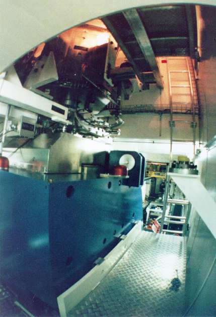
Two wide angle pictures taken from the platform on one side of the big 64 degs
bending magnet (AHO, weight = 50 tons) are shown in
Fig.7 (33 kB) and
Fig.8 (34 kB) . They both give
some good impression of the component's 3D-arrangement. The bending magnets are
blue and the QHI quadrupoles are red and the 3 last ones (QHJ) are nickel
plated. In the background one can see the yellow 25 ton crane. Compare also
with Fig.1 (43 kB) , where the same
color code is used and where nickel plated magnetic components (radiation
hardened) are colored in grey.
Some interesting historic facts about the PSI high current proton
beam developments and the commissioning of the SINQ in 1996
were presented in an article at the PAC97.
A non-trivial problem of this proton beam line is the fraction of the proton beam, which may miss the
target E (lateral dimension = 6 mm) caused by some occasional wrong steering of the proton beam
leaving the 590 MeV ring cyclotron. This proton beam will be non-scattered by the graphite material of target E
and therefore has more momentum (dp = 21/32 MeV/c for a 40/60 mm long target). Computations show, that
this leads unfortunately to 10-20 times higher current density for the non-scattered proton beam component at
the SINQ target.
To avoid this, an electronic beam transmission device, which monitors the proton beam intensity
before and after target station E (MHC4 and MHC5) computes the beam transmission permanently and triggers
an interlock signal in case too much proton beam is bypassing target E. In order to get more redundancy
in detecting the proton beam bypassing target E, a second method which stops the wrong proton beam at the dispersive
focus inside QHJ30 has been realized recently (2003). This redundancy is
considered as crucial for the safety requirements during the planned operation of the MEGAPIE
experiment.
horizontal- and
2 vertical-cut). The shown profiles are
typical for this proton beam line and all but gaussian in shape (specially MHP55 in x,
Fig.2: 8 kB ).
The shown envelope fit displays
the proton beam at 900 µA during the commissioning of this new proton beam line on
Dec 4, 1996 (see Fig.3: 22 kB ).
(Note that x and y half-panes are interchanged here.) In order to get this
relatively good fit, the effective length of the first 4 quadrupoles (QHGs) had
to be changed from 630 (stemming from field measurements) to 644 mm. This
2 % stretching of the field length is probably due to the iron of the steering
magnets (SHGs), which are squeezed between the two quadrupoles forming a
duplet. How well the parameterization of this proton beam line is understood is
demonstrated
in Fig.4 (23 kB) which shows
the results of a proton beam centroid shift fit produced by
varying the currents through the bending magnet AHL and the steering magnet
SHG21x and by using the measured changements in proton beam position at the different
profile monitor locations (+) as fit constraints.
The proton beam losses at the target station E and the nearby collimators sum up to about 43 %
(for 60 mm C target) or 30 % (for 40 mm C target). After the slits KHN21x and
KHN22y (which act as proton beam halo scrapers, see
Fig.5 [25 kB]) and the long drift tube the
sum of the losses along the remaining 25 m of the proton beam line are very low
(10 ppm). The losses have been computed with the Monte Carlo program Turtle.
The results stemming from 10 million particles passing through the proton beam line are
displayed graphically in a logarithmic Excel diagram
( Fig.6: 15 kB ) . It should be
mentioned here, that the blow up at target E and the subsequent cut-off at the
collimators is required in order to achieve a proton beam diameter of 10 cm at the SINQ
target and at the same time low losses down in the proton beam line cellar. Target E
thickness reductions from 60 mm to 40 mm makes an operation
under the above mentioned conditions still possible, but of course at the
expenses of some of the Pion and Myon Physics experiments (of which the event
rate is proportional to the length of target E).
Two wide angle pictures taken from the platform on one side of the big 64 degs
bending magnet (AHO, weight = 50 tons) are shown in
Fig.7 (33 kB) and
Fig.8 (34 kB) . They both give
some good impression of the component's 3D-arrangement. The bending magnets are
blue and the QHI quadrupoles are red and the 3 last ones (QHJ) are nickel
plated. In the background one can see the yellow 25 ton crane. Compare also
with Fig.1 (43 kB) , where the same
color code is used and where nickel plated magnetic components (radiation
hardened) are colored in grey.
Some interesting historic facts about the PSI high current proton
beam developments and the commissioning of the SINQ in 1996
were presented in an article at the PAC97.
A non-trivial problem of this proton beam line is the fraction of the proton beam, which may miss the
target E (lateral dimension = 6 mm) caused by some occasional wrong steering of the proton beam
leaving the 590 MeV ring cyclotron. This proton beam will be non-scattered by the graphite material of target E
and therefore has more momentum (dp = 21/32 MeV/c for a 40/60 mm long target). Computations show, that
this leads unfortunately to 10-20 times higher current density for the non-scattered proton beam component at
the SINQ target.
To avoid this, an electronic beam transmission device, which monitors the proton beam intensity
before and after target station E (MHC4 and MHC5) computes the beam transmission permanently and triggers
an interlock signal in case too much proton beam is bypassing target E. In order to get more redundancy
in detecting the proton beam bypassing target E, a second method which stops the wrong proton beam at the dispersive
focus inside QHJ30 has been realized recently (2003). This redundancy is
considered as crucial for the safety requirements during the planned operation of the MEGAPIE
experiment.
| [1] K. Deiters, F. Foroughi, G. Heidenreich, U. Rohrer, Reduction of Target E Length from 60 mm to 40 mm. PSI Scientific and Technical Report 1999, Volume VI (Large Research Facilities), p. 26-27. |
| The proton losses along the proton beam line were computed with the computer code Turtle which is available electronically for various PC operating systems. |
 590 MeV High Intensity Proton Beam Lines: Home Page.
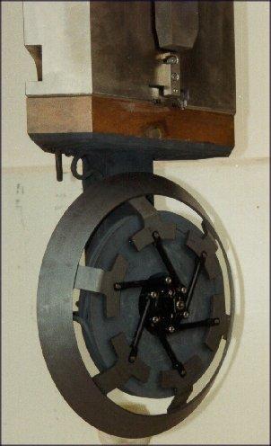
![Fig.5 [25 kB]](moregifs/scrapers.gif)
![]()
![]() Last updated by
Urs Rohrer on 28-Jun-2006
Last updated by
Urs Rohrer on 28-Jun-2006